| Oracle® Transparent Gateway for DRDA Installation and User's Guide 10g Release 2 (10.2) for Microsoft Windows Part Number B16218-03 |
|
|
PDF · Mobi · ePub |
| Oracle® Transparent Gateway for DRDA Installation and User's Guide 10g Release 2 (10.2) for Microsoft Windows Part Number B16218-03 |
|
|
PDF · Mobi · ePub |
This chapter describes configuration of the IBM Communication Server product on MS Windows for use with the Oracle Transparent Gateway for DRDA. IBM Communication Server provides SNA connectivity through the APPC/LU6.2 protocol between the host and the remote DRDA Server. Read this chapter to learn more about creating Communication Server profiles.
This chapter contains the following sections:
This chapter requires you to enterparameters unique to your system in order to properly configure the IBM Communication Server. Refer to Appendix E for a worksheet listing all the installation parameters that you will need to know before you can complete the configuration process. Ask your network administrator to provide you with these parameters before you begin.
Step 1: Creating IBM Communication Server Profiles for the Gateway
Step 2: Definition Types
Step 3: Testing the Connection
The Oracle Transparent Gateway for DRDA requires a stored set of definitions, called Side Information Profiles, to support connections between the gateway and DRDA Servers. Each profile consists of a profile name and a profile type, a set of fields describing the profile. The fields in a given profile type are generally a mixture of operating parameter values and names of other SNA profiles relevant to the profile. Each functional part of APPC, such as the Mode, Remote Transaction Program (RTP) name, and Logical Unit (LU), is described by a distinct profile type.
Oracle recommends independent LUs for the Oracle Transparent Gateway for DRDA, because they support multiple parallel sessions or conversations. This means multiple Oracle client applications can be active simultaneously with the same DRDA Server through the independent LU.
Dependent LUs support only one active session. The CP (IBM Communication Server, in this case) queues additional conversation requests from the gateway server behind an already active conversation. In other words, conversations are singleEthreaded for dependent LUs.
If a dependent LU is correctly defined, then no alterations to the Oracle Transparent Gateway for DRDA configuration are needed, nor should any changes be needed to the DRDA Server.
The operational impact of dependent LUs is that the first client application can start a conversation through the gateway with the DRDA Server. While that session is active (which could be seconds, minutes, or hours, depending on how the client application and transaction are designed), any other client application starting a session with the same DRDA Server appears to stop responding as it waits behind the previous session.
If a production application really uses only one conversation at any one time, then there should be no impact. However, additional concurrent conversations might be required for testing or other application development. Each requires that additional dependent LUs be defined on the remote host, plus additional IBM Communication Server configuration entries which define the additional dependent LUs on the host.
Additional Side Information Profiles should be defined to use the new dependent LUs. New Transparent Gateway for DRDA instances should be created and configured to use these new Side Information Profiles.
IBM Communication Server definitions are created using the SNA Node Configuration tool, while the actual operation of the server is done using the SNA Node Operations tool, both of which are provided with IBM Communication Server. Maintenance of SNA definitions is normally done by a user with Administrator authority.
The tg4drda\sna\commsvr subdirectory contains a sample set of IBM Communication Server definitions created with the SNA Node Configuration tool. The oracle.acg file contains sample definitions for IBM Communication Server.
Before building the IBM Communication Server definitions, examine the oracle.acg file to determine the definitions needed, their contents, and their interrelationships. The file format is textEoriented and each field of each definition is clearly labeled. You can print a copy of the file to use while working with your definitions in an SNA Node Configuration session.
There are several types of IBM Communication Server definitions relevant to gateway APPC/LU6.2 operation. Each definition can be created and edited using a corresponding SNA Node Configuration menu.
The definitions relevant to the gateway are presented here in hierarchical order. Those definition types that are lowest in the hierarchy are discussed first. This matches the logical sequence in which to create the profiles.
Refer to the IBM Communication Server online documentation for a complete discussion of IBM Communication Server definitions. This section is an overview of IBM Communication Server definitions in relation to the Oracle Transparent Gateway for DRDA.
This section describes the process of creating SNA definitions for IBM Communication Server using the SNA Node Configuration tool. All the tasks described in this section are performed within SNA Node Configuration.
Figure 7-1 Choosing a Configuration Scenario
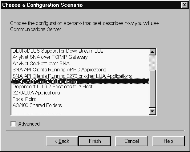
SNA Node Configuration will first ask if you are creating a new configuration or loading an existing configuration. The following example is presented with the assumption that a new configuration is being created.
SNA Node Configuration will next prompt you for a configuration scenario. Our example is made assuming that a CPIEC or APPC scenario is being chosen.
Figure 7-2 Creating the Node Configuration
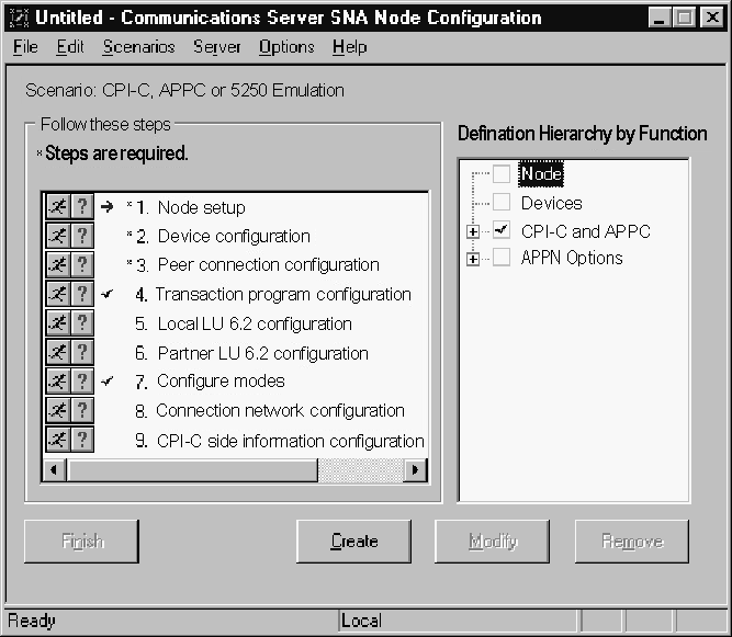
Each SNA Server must have a Control Point defined. This is typically called the Node definition. Click Node and click Create.
In the Define the Node dialog box, in the Basic tab, enter the Control Point, Local Node ID, and Node Type information. You can also select option in the Advanced tab depending on your SNA network configuration. Click OK.
Communication devices should be configured next. Select Devices, and click Create.
Select the type of device to use for communication. The LAN type is typical for either Ethernet or TokenEring attached network devices.
In the Basic tab, select the adapter to use and the local SAP. The other tabs may be explored for network tuning parameters. Click OK.
Peer connections should be configured next. Select Peer Connections, and click Create.
In the Basic tab, enter a link station name for this connection. Choose the Device for the connection, and enter the destination address and remote SAP.
Select the Adjacent Node tab. Enter the Adjacent CP name of the remote system and pick its CP Type. You may have to choose a different Transmission Group (TG) as the default. Consult your SNA Network Administrator for details. The other tabs may be explored for tuning and link reactivation options. Click OK.
Next, define the local LUs for this Node. Select Local LU 6.2 LUs, and click Create.
In the Basic tab, enter the name of the local LU and an alias, if desired. The name must match the Local LU definition of the remote host for this node. The Advancedtab may be explored for Synchronization support and for LU session limits. Click OK.
Next, define remote Partner LUs for this Node to connect to. Select Partner LU 6.2 LUs and click Create.
In the Basic tab, enter the name of the remote or partner LU and an alias, if desired. Seclect Fully Qualified CP from the existing list. The Advanced tab may be explored for logical record limits and security support. Click OK.
Next, define the IBMRDB mode, which will be used for DRDA connections. Select Modes and click Create.
In the Basic tab, enter the name IBMRDB and the mode session limits. Consult your SNA Network Administrator for details. The Advanced tab may be explored for pacing and autoactivation session options. Click OK.
Figure 7-16 Create the CPIEC Side Information Profile
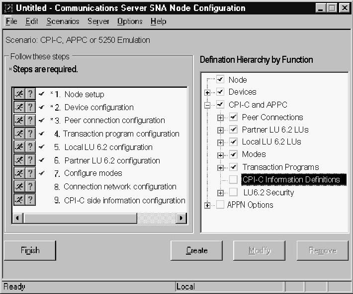
Next, define the CPIEC profile that will be use dby the gateway. Select CPIEC side information definitions and click Create.
Figure 7-17 Define the CPIEC Side Information Profile
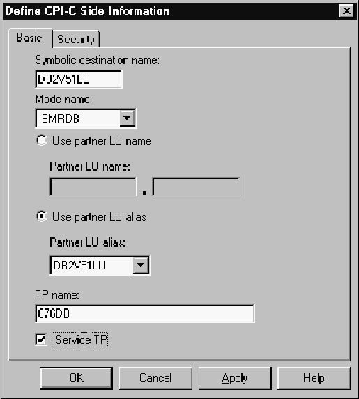
In the Basic tab, enter the Symbolic Destination name. Select IBMRDB for the Mode name drop-down list, and select the Partner LU either by name or by alias. Enter the TP name for the remote DRDA Server. Mode DRDA Servers use the default Service TP name X'07F6C4C2' or '076DB'. Consult your DRDA Server Administrator for the correct TP name. The Advancedtab may be explored for security options.
Note:
TheDRDA_CONNECT_PARM should be assigned the name of the Symbolic Destination name as entered in Figure 7-16, "Create the CPIEC Side Information Profile".Before proceeding with the gateway configuration tasks in Chapter 10, "Configuring the Gateway", ensure that your connection is working. This can be done by using the SNA Node Operations tool.
Figure 7-18, "Relationship Between IBM Communication Server Definitions and Host VTAM Definitions" shows the relationship between IBM Communication Server definitions and the VTAM definitions on the host.
Figure 7-18 Relationship Between IBM Communication Server Definitions and Host VTAM Definitions
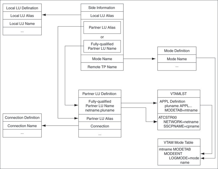
When the database link request for the gateway begins, the gateway attempts to start an APPC conversation with the DRDA Server. Before the conversation can begin, a session must start between the host LU and the DRDA Server LU.
SNA and its various access method implementations (including IBM Communication Server) provide security validation at session initiation time, enabling each LU to authenticate its partner. This is carried out entirely by network software before the gateway and server application programs begin their conversation and process conversationElevel security data. If sessionElevel security is used, then correct password information must be established in the Pentium-based host Connection Profile and in similar parameter structures in the DRDA Server system that is to be accessed. Refer to Microsoft SNA Server and IBM Communication Server product documentation for detailed information.
SNA conversation security is determined by the setting of the gateway initialization parameter, DRDA_SECURITY_TYPE. This parameter determines whether SNA security option SECURITY is set to PROGRAM or to SAME. Generally, the gateway operates under SNA option SECURITY=PROGRAM, but it can also be set to operate under SNA option SECURITY=SAME.
If DRDA_SECURITY_TYPE=PROGRAM is specified, then the gateway allocates the conversation with SNA option SECURITY=PROGRAM and sends this information to the DRDA Server:
If the database link has explicit CONNECT information, then the specified user ID and password are sent.
If the database link has no CONNECT clause and if the application has logged in to the Oracle integrating server with an explicit user ID and password, then the Oracle user ID and password are sent.
If the application logs in to the Oracle integrating server with operating system authentication and if the database link lacks explicit CONNECT information, then no user ID and password are sent. If no user ID and password are sent and if the DRDA Server is not configured to assign a default user ID, then the connection fails.
In general, SECURITY=PROGRAM tells the DRDA Server to authenticate the user ID/password combination using whatever authentication mechanisms are available. For example, if DB2/OS390 is the DRDA Server, then RACF can be used. This is not always the case, however, because each of the IBM DRDA Servers can be configured to process inbound user IDs in other ways.
The SECURITY=SAME option is not directly supported by IBM Communication Server. SECURITY=SAME implicitly validates security by using the user account under which the TNS listener was started. IBM Communication Server, however, does not support this type of validation.